一. Driving system diagram
The driving system diagram is as follows:

二. Energy saving scheme
According to the situation, the energy saving scheme is as follows:

Because the main source of renewable power is the lifting potential energy and the kinetic energy of walking, so we need to save energy for two main frequency converters and a large car inverter.
三. Energy saving system
1. The first system diagram of the energy saving device is as follows:

2. Input end protection
The energy saving system has a series of protection on the DC input of the driving frequency converter, and the protection block diagram is as follows:

Not only in high voltage input reverse, inverter DC bus to meet the requirements of insulation insulation, energy-saving system requirements, driving inverter normal boot, input protection system will start the pre charging circuit, the inverter DC bus and DC bus energy saving device friendly parallel, and does not impact current system input, in the pre the normal charge and energy saving device of DC bus voltage is precharged to the frequency converter and the DC bus voltage is equal to the basic situation, the system will pull the energy saving device of high voltage switch, high voltage input terminal connected energy-saving device and inverter DC bus system, running on the normal energy state.
When the vehicle is stopped or overhauled, once the inverter is cut off, the energy saving system will soon detect the high voltage undervoltage and quickly disconnect the high-voltage switch. The input protection system will start immediately, perform the power loss protection, disconnect the pre charge circuit, and completely disconnect from the inverter.
At the same time, the energy saving device will always monitor the insulation of the DC system before and during the operation of the high voltage switch. Once the insulation is reduced, it will immediately stop the operation of the energy saver and alarm instructions. The insulation monitoring system can not only protect the energy saver system, but also help users monitor the DC to ground insulation of the inverter, which has a good reference value for the users, which is equivalent to a good function supplement for the inverter motor protection.
3. DC/DC protection
120A Technical parameters of bi-directional DC/DC
|
number
|
category
|
Detailed
|
Specifications
|
|
1
|
DC voltage
|
High voltage side DC voltage(Vdc)
|
400-750
|
|
Low voltage DC voltage(Vdc)
|
200—500
|
|
2
|
DC current
|
HVDC current(A)
|
<=120A
|
|
Low voltage DC current(A)
|
<=120A
|
|
3
|
conversion efficiency
|
Enter 600V, output 300V
|
95%
|
|
4
|
Rated power
|
Output power (output voltage 400V)
|
50KW,Maximum power 60KW
|
|
5
|
The rated power
|
RS485,modbus rtu
|
230A two-way DC/DC technical parameter
|
number
|
category
|
category
|
Specifications
|
|
1
|
DC voltage
|
High voltage side DC voltage(Vdc)
|
400-750
|
|
Low voltage DC voltage(Vdc)
|
200—500
|
|
2
|
DC current
|
HVDC current(A)
|
<=230
|
|
Low voltage DC current(A)
|
Rated 230, maximum 250
|
|
3
|
conversion efficiency
|
Enter 600V, output 300V
|
95%
|
|
4
|
Rated power
|
Output power (output voltage 400V)
|
100KW, maximum 120KW
|
|
5
|
communication interface
|
RS485,modbus rtu
|
DC/DC The protection function is as follows:
|
number
|
category
|
category
|
|
1
|
Hardware protection
|
Overcurrent release protection of high voltage switch
|
|
1.25 times rated overcurrent fuse protection for high voltage DC fuse
|
|
2
|
Current limiting protection
|
DC/DC strictly enforces the current limiting, limiting current not exceeding the rated current
|
|
3
|
Overcurrent protection
|
DC/DC performs protection when the current can not be limited to current and exceeds the over current value
|
|
4
|
Voltage protection
|
High voltage overvoltage, high voltage undervoltage, low pressure overvoltage, low pressure undervoltage
|
|
5
|
Overheating protection
|
DC/DC detects the stability of each IGBT module and performs protection when overheating values
|
|
6
|
Overheating protection
|
When the temperature of the environment is lower than the starting temperature of the energy saving device, the energy saving device does not start
|
|
7
|
IGBT protection
|
After any IGBT newspaper fails, the corresponding DC/DC will stop running
|
|
8
|
Overcapacity protection
|
After the overcapacity module is reported to fail, all DC/DC will stop running
|
4. Supercapacitor monitoring and protection
The super capacitor energy storage system has a perfect protection monitoring system, and the protection block diagram is as follows:

Each overcapacity module has a sampling system inside, and a thermistor probe (NTC) is installed for the temperature of 18 internal hypercapacitors. The voltage of each monomer is monitored. We will make every three overcapacity modules as a unit for centralized monitoring. The super capacity monitoring panel will collect the sampled signal of the module into a protective signal, transmit it to the next level, and finally transmit it to the energy saving control system. Any overcapacity monomer has failed. The energy saver will stop working and report the fault signal. The corresponding overcapacity monitoring board will indicate the fault overcapacity module with the indicator light.
四. Capacitor configuration of energy saving device
4.1 basic energy storage unit
The supercapacitor energy storage unit of the energy saving device selects the 3000F/2.7V capacitive monomer, and every 18 capacitive monomers are excited by the manufacturer.
The light welding is connected to the 166F/48V capacitor module, so the basic energy storage unit is the overcapacity module.
4.2 overcapacity module configuration
According to field investigation and consulting factory workers, are known driving parameters:
Quality of wire rope and hook: 2 tons;
Fixture quality: 20 tons;
Hoisting steel plate quality: 70 tons;
Raise the height below: 3-4m, according to 3m.
A period of operating period jig down 3M, full load up 3M, full load down the 3M, jig up 3M.
The energy recovery device is gravity potential energy, that is, the regenerative electricity generated by the clamp down detection and the regenerative electricity generated by full load and downhole exploration. If the energy storage type energy saver needs to absorb all potential energy, it must meet the energy generated by the excess capacity storage energy, which is greater than or equal to the energy generated by full load and downhole exploration.
The regenerated energy at full load is W1 = MGH = 92000 * 9.8 x 3 = 2704.8KJ;
Taking into account the power generation efficiency, motor system efficiency and average load rate, the maximum energy recovery is =0.7, W2:
W2= * W1= 0.7 * 2704.8=1893KJ
A single overcapacity module has a voltage range of 18V-48V, and the storage energy is 164KJ.
Therefore, the number of energy saving device configuration module is 11 groups, which can store the energy 1804KJ.
4.3 DCDC configuration
Two lifting converter configuring 2 230A DCDC, large car inverter configuration 1 120A DCDC, total configuration DCDC basic 120A module 5.
五. Prediction of energy efficiency (economic benefit)
1. full load of potential energy
W2=1800KJ=0.5KWH
The potential energy of 2. jig
W3=0.7*22000*9.8*3=453KJ=0.125KWH
3. power saving calculation
An operating cycle energy saving: 0.5+0.125=0.625KWH
Operation 28 times per hour: 0.625*28=17.5KWH
One day power: 420KWH
For 300 days a year, the amount of electricity is 126 thousand KWH
六. Social results
Single driving implementation of energy saving, energy-saving 126 thousand, equivalent to
Annual saving of standard coal: 42 tons;
Annual reduction of CO2 emissions: 125 tons;
The reduction of SO2 emissions by 3.8 tons in the year;
Reduce the emission of nitrogen oxides by 1.9 tons;
It is equivalent to 1000 mu of tree planting in the year.
七. Similar case
We use a similar case in the harbor to illustrate the efficiency of energy saving.
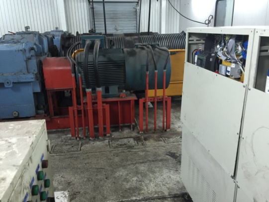
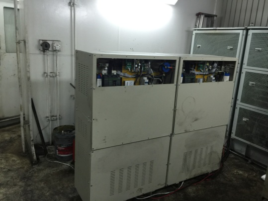
1. Weihai port door machine installation site


2. Energy saving system diagram of Weihai port gate machine

Lifting support for energy saving system diagram of frequency converter
3. Energy saving effect test
(1)Test plan: when the energy saver doesn't put into operation, it uses the power analyzer to test the 220KW converter (lifting and supporting), the input terminal E1, then the energy saver is put into operation, and then the 220KW converter (lifting support) input terminal power E2 is tested by the power analyzer. The energy saving rate is as follows: 。
。
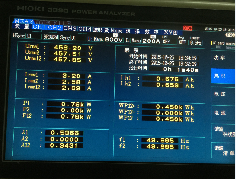
(2) test instrument: Japanese original imported high precision power analyzer: HIOKI 3390.
(3) test cycle: five working cycles.
(4) test conditions: coal unloading, coal loading, vertical lifting.
(5) test data
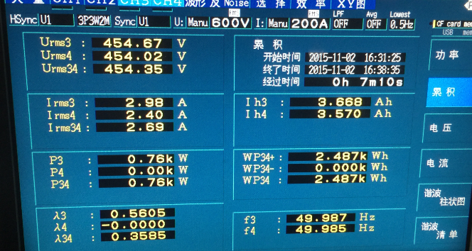
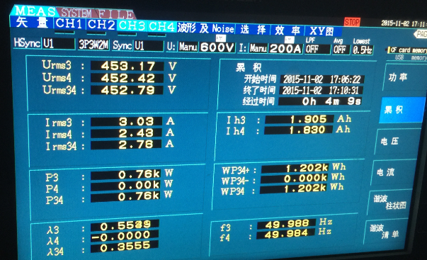
When the A. crane is unloaded, the daily power analyzer 3390 has been used to test the power saving rate

Lift to support the opening of the energy saving device Rise to support the shutdown of the energy saving device
The contours of coal unloading, lifting support saving rate =  = 34.7 %
The above test is based on a single operation cycle, and the rate of electricity saving will be different because of the different working conditions and different operation.
When the B. crane is loaded to the ship, the daily power analyzer 3390 has been used to test the power saving rate

Lift to support the opening of the energy saving device Rise to support the shutdown of the energy saving device
From the figure out loading, lifting support saving rate =  = 48.1 %
The above tests are based on 5 loading cycles of the ship to the ship. Due to the different operating conditions and different operation, the electricity consumption will be different.
C. crane vertical lifting operation, 3390 tested the saving rate by HIOKI power analyzer: crane drive 8 ton bucket, from the ground up to the limit position, and then on the ground, five times as a test cycle.

Lift to support the opening of the energy saving device Rise to support the shutdown of the energy saving device
Can be obtained by VTOL, lifting support saving rate =  = 40.1 %
The above tests are based on 5 vertical lifts, manual operation, and height error within 1 meters.
(6) summary of energy saving
According to the results of the test, we can draw the following conclusions:
Average coal saving rate = 48.1%
The average electricity saving rate of coal unloading = 34.7%
Loading and unloading of non dust cargo (equivalent to vertical lift and electricity saving rate) = 40.1%