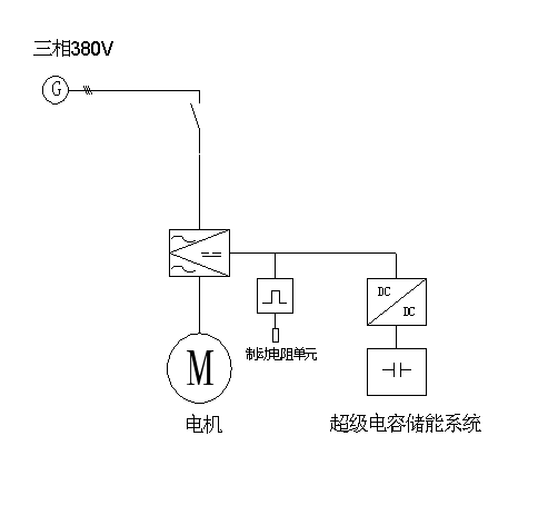
一. Application system diagram
According to customer requirements, configuration of the system chart is as follows, for reference only.

二. system description
1., the supply range of DC/DC is: the above is the user interface of the DC/DC, the 2 terminals of the high voltage terminal, 2 of the low voltage terminals, and one of the auxiliary power supply interfaces of the 220Vac.
2. 220Vac auxiliary power supply range: 86-260Vac;
3. voltage range of high voltage end: 450-800Vdc;
4. voltage range of low voltage end: 60-450Vdc;
The 5. DCDC high voltage end must be connected with the converter DC bus, and the low voltage end is connected with the supercapacitor system.
6. the original brake unit of the frequency converter must be kept;
7. charge discharge current is less than 40A, can automatically charge or discharge, does not require an external controller to complete the energy-saving function, has the advantages of energy saving electricity accumulation function.
三. DCDC Specifications
|
Number
|
category
|
detailed
|
Specifications
|
|
1
|
DC voltage
|
High voltage side DC voltage(V)
|
450-800Vdc (Can be set up)
|
|
Low voltage DC voltage(V)
|
60—450Vdc (Can be set up)
|
|
2
|
DC current
|
High voltage DC current(A)
|
<=40A
|
|
Low voltage DC current(A)
|
<=40A
|
|
3
|
conversion efficiency
|
High voltage 600V, low voltage 300V
|
95%
|
|
4
|
Rated power
|
Output power (low voltage voltage 200V)
|
Rated 8KW, maximum instantaneous power 16KW
|
|
5
|
communication interface
|
RS485,Full isolation
|
Modbus,RTU Agreement
|
|
6
|
size
|
279*185*240(mm)(Length * width * height)
|
|
7
|
weight
|
8KG
|


